Manufacturer must ask the label printer to provide finished printed labels with UL required markings.
Manufacturer needs to print UL required markings by specific inks and compatible printing equipment to the label materials. [supplementary Information]
GCS Safety Team
0 Comments
Based on UL 746C[Note], polymeric material maintains the relative positioning of live parts or encloses live parts shall be subjected the Impact Test.
In accordance with the use of electrical equipment, there are two impact test procedure for polymeric materials in UL 746C. 1. Standard: UL 746C 2. Test Name: Resistance to Impact Test 3. Method: (1) Drop Impact Test Hand-supported equipment (2) Ball Impact Test Permanently wired equipment, or floor-supported equipment or equipment not likely to be dropped during intended use [Note] UL 746C: Polymeric Materials – Use in Electrical Equipment Evaluations GCS Safety Team 1. Test Name
- UL: Dielectric Voltage Withstand Test / DVW Test - CSA: Dielectric Strength Test - CE / EN: Electric Strength test - Manufacturer: High Potential Test / Hi-Pot Test 2. Purpose The test is used to verify that the electrical insulation (spacings, solid insulation…) of components and of assembled appliance has adequate dielectric strength to resist overvoltage conditions. 3. Instrument Dielectric Tester / Puncture Tester 4. Method -The testing appliance is disconnected from the supply. -A sinusoidal voltage at specified frequency and high voltage is applied for 1 min between: (1) primary wiring and accessible dead-metal parts that are likely to become energized; (2) primary wiring and secondary wiring. -For the test the potential is started at zero and gradually increased to the final value where it is held for 1 min. 5. Result The appliance withstood the test potential without breakdown for 1 min. GCS Safety Team 【Safety Certification】The Clearances, Creepage Distances and Solid Insulation in Product Safety12/2/2020 Appliances shall be constructed so that the clearances, creepage distances and solid
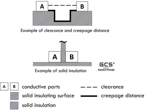
insulation are adequate to withstand the electrical stresses to which the appliance is liable to be subjected. Do you know the different for clearances, creepage distances and solid Insulation?
Examples of Insulation The conductive parts A and B are mounted on solid insulating material surface. Clearance is the "line of sight" distance. Creepage distance path follows the contour of the groove. [Note] Reference Safety Standard: - IEC/EN 60664-1 Insulation coordination for equipment within low-voltage systems – Part 1: Principles, requirements and tests GCS Safety Team The insulation shall be applied to live parts to provide protection against electric shock.
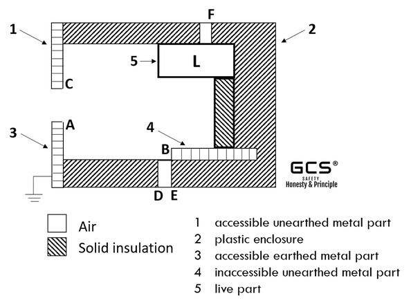
Do you know the insulation requirement between live parts and enclosure openings? Please see the following for examples.
[Note] If the insulation L & B meet the requirements for reinforced insulation, the insulation B & E of supplementary insulation are not measured.
- L & F Examples of Insulation The live part L is partially surrounded by a plastic enclosure containing openings, partially by air and is in contact with solid insulation. A piece of inaccessible metal is incorporated inside the construction. There are two metal covers, one of which is earthed. [Note] Reference Safety Standard: - IEC/ EN 60335-1 Household and similar electrical appliances – Safety – Part 1: General requirements GCS Safety Team Based on IEC/ EN 60335-1, the general requirements for household and similar electrical appliances, the insulation shall be applied to live parts and metal parts to provide protection against electric shock.
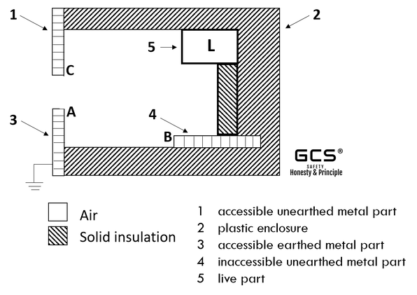
Do you know the insulation requirement between live parts and different metal parts?
Examples of Insulation The live part L is partially surrounded by a plastic enclosure, partially by air and is in contact with solid insulation. A piece of inaccessible metal is incorporated inside the construction. There are two metal covers, one of which is earthed. [Note] Safety Standard - IEC/ EN 60335-1 Household and similar electrical appliances – Safety – Part 1: General requirements GCS Safety Team The Classification System that found in Article 506:
- divides locations having dusts, fibers or flyings into Zones (20, 21 & 22). ZONES: - Zone 20: a location where ignitible concentrations are present continuously or for long periods of time under normal operating conditions. - Zone 21: a location where ignitible concentrations are likely to exist occasionally under normal operating conditions. - Zone 22: a location where ignitible concentrations are not likely to exist under normal operating conditions. [Note] - NEC - National Electrical Code of USA - Article 506 covers the requirements for the zone classification system as an alternative to the division classification system covered in Article 500, Article 502 (Class II Locations) and Article 503 (Class III Locations) for electrical and electronic equipment and wiring for all voltages in Zone 20, Zone 21 and Zone 22 hazardous (classified) locations where fire and explosion hazards may exist due to combustible dusts, or ignitible fibers or flyings. Combustible metallic dusts are not covered by the requirements of this article. GCS Safety Team The Classification System that found in Article 505:
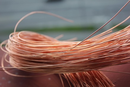
- divides locations having gases and vapors into Class I, Zones (0, 1 & 2) and Gas Groups (IIA, IIB & IIC). CLASS I Locations where fire or explosion hazards may exist due to flammable gases, vapors, or liquids. ZONES: - Zone 0: a location where ignitible concentrations are present continuously or for long period of time under normal operating conditions. - Zone 1: a location where ignitible concentrations are likely to exist under normal operating conditions. - Zone 2: a location where ignitible concentrations are not likely to exist under normal operating conditions. MATERIAL GROUPS: - Group IIA – A typical material is propane. - Group IIB – A typical material is ethylene. - Group IIC – A typical material is hydrogen, Acetylene. [Note] - NEC - National Electrical Code of USA - Article 505 covers the requirements for the zone classification system as an alternative to the division classification system covered in Article 500 for electrical and electronic equipment and wiring for all voltages in Class I, Zone 0, Zone 1 and Zone 2 hazardous (classified) locations. GCS Safety Team Generally speaking, there are two choices can be used, if you want to apply the magnet wire UL Certification.
Choice 1: Use Non-UL Recognized Magnet Wire Coating. Magnet wires constructed from Non-UL Recognized magnet wire coatings shall be subjected to a full thermal aging program [note] and the heat shock, dielectric strength, and qualitative infrared analysis tests. [note] Typically, full thermal aging program in three-temperature aging requires approximately a year or more to complete. Choice 2: Use UL Recognized Magnet Wire Coating. Magnet wires constructed from UL Recognized magnet wire coatings shall be subjected to a one-temperature thermal aging program and the heat shock, dielectric strength, and qualitative infrared analysis tests. In view of the UL Certification service fee, time, sample requirements and the risk of testing, GCS Safety suggest you to use UL Recognized Magnet Wire Coating for your Magnet Wire UL Certification.
- OBNT2, Magnet Wire Coatings GCS Safety Team  The classification system that found in Article 500: - divides all hazardous (classified) locations into Classes (I, II & III), Divisions (1 & 2) and Groups (A, B, C, D, E, F & G). CLASSES: - Class I locations are those in which flammable gases or vapors are or may be present in the air in quantities sufficient to produce explosive or ignitible mixtures. - Class II locations are those that are hazardous because of the presence of combustible dust. - Class III locations are those that are hazardous because of the presence of easily ignitible fibers or flyings, but in which such fibers or flyings are not likely to be in suspension in the air in quantities sufficient to produce ignitible mixtures. DIVISIONS: - Division 1 is a location where an ignitible concentration of a flammable or combustible material is present under normal operating conditions. - Division 2 is a location where an ignitible concentration of a flammable or combustible material is present only under abnormal operating conditions. MATERIAL GROUPS: - Class I Group Classifications: Group A – Acetylene. Group B – A typical Class I, Group B material is hydrogen. Group C – A typical Class I, Group C material is ethylene. Group D – A typical Class I, Group D material is propane. - Class II Group Classifications: Group E - Metal dusts. Group F - Carbonaceous dusts. Group G - Combustible dusts not included in Groups E or F. [Note] NEC - National Electrical Code of USA GCS Safety Team |


